
NordCarolina Blog
Formerly BoostMoose.com
11-16 Ford F250 / F350 Super Duty - Definitive Flow-Through Center Console Install Guide
FOREWARD
On the 2011 - 2016 F-Series Super Duty trucks, the lower end models were specced with a front bench seat, with the folding middle seat also serving as a center console. These serve their purpose, however people may find the cup holders to be lacking, and the dead space a bit of a waste by their feet. In this guide we will be going over everything you need to know and do, to properly install one of these center consoles.
PREREQUISITES
For this job we will need the following tools and items:
Socket Set (Sizes from 5mm to 21mm are needed)
1/4, 3/8, and 1/2 wrenches / impact drivers
Various socket extensions
Screw drivers
Picks / Trim Tools
Wire Strippers (and wire + solder joints / soldering iron)
Misc. other tools may be needed
Items to order:
Dash Bezel: BC3Z-2504608-CB
Airbag Control Bezel: BC3Z-25047A04-BA
Obviously you will also need a complete center console, however they can no longer be ordered new from Ford and will have to be found on a local marketplace. Make sure to check the one you buy comes with all the various bolts, covers, brackets, etc.
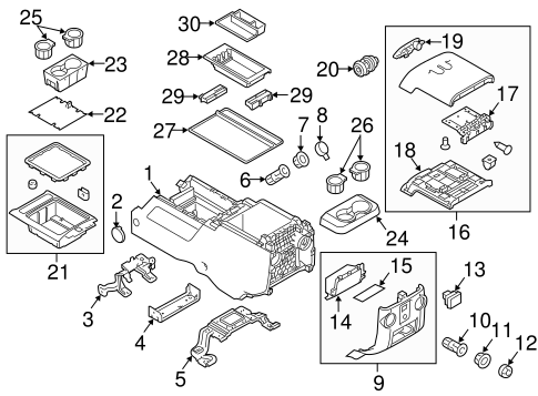
For the full diagram with parts, go here: https://www.oemfordpartsdirect.com/v-2013-ford-f-250-super-duty--xl--6-2l-v8-flex/body--front-console
We will be referring back to this diagram at certain points in the install.
Build Process
Center Console Prep
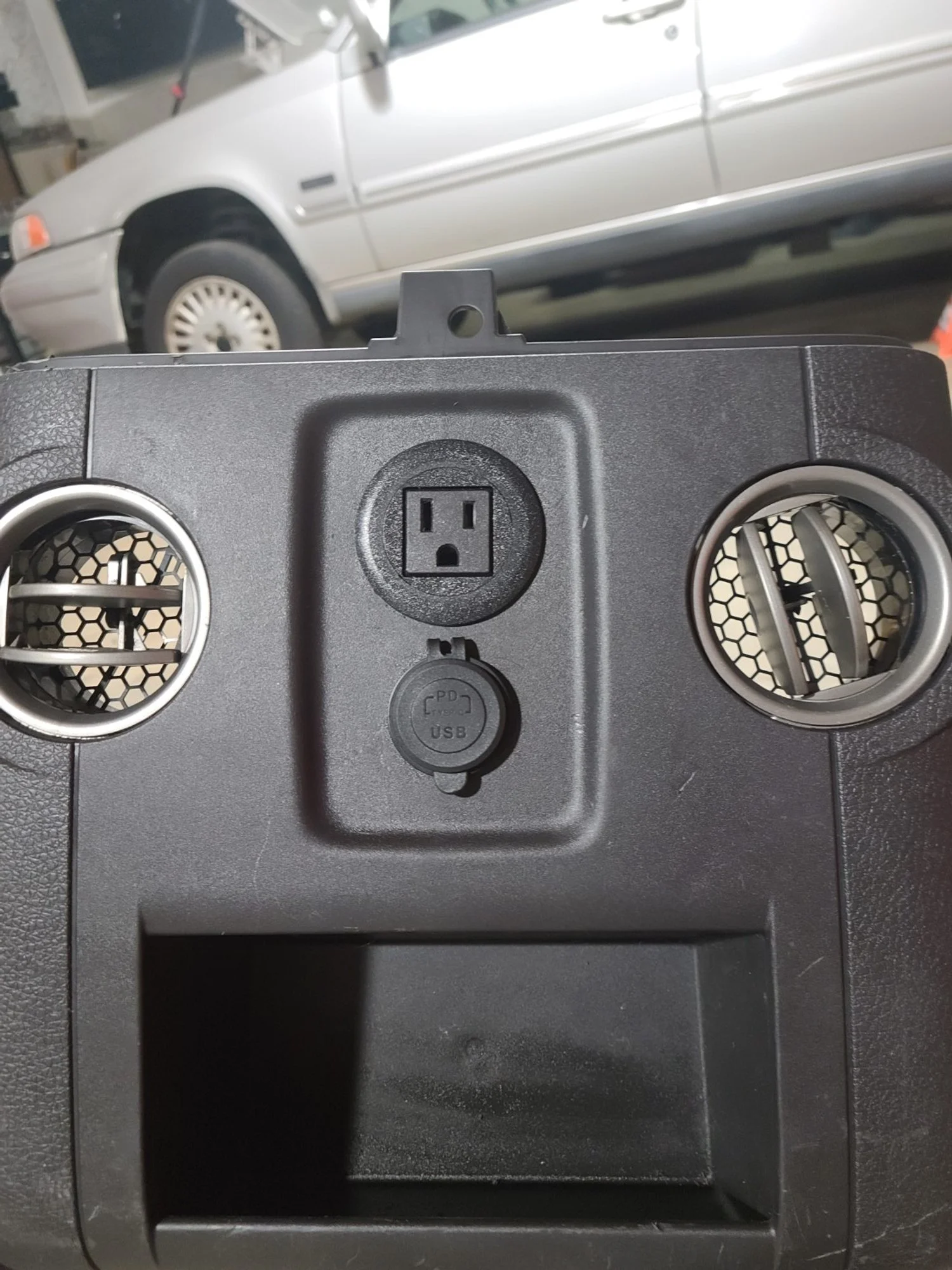
From the factory, the flow through console has 3 additional power ports installed. 1 110V inverter outlet, and 2 standard 12v lighter sockets. On higher trim trucks, there is a harness under the carpet that runs to single plug on the side of the console to give these ports power. However on a XL trim truck, such harness is not there. Additionally the inverter needs a CANBUS signal to turn on and off, which can be a pain when trying to integrate the OEM inverter. For this project, I ended up buying a basic inverter off Amazon, which had the same 150W output as the stock inverter. (Its worth noting this is a very small amount of wattage, and a much beefier inverter could be easily fit into the large space of the center console for powering high wattage power tools).
In the above diagram, I removed panel 9 to replace he 110V plug and the lighter socket. Since the OEM 110 plug has a proprietary harness, I replaced it with a “screw in” type that is designed for a desk or other flush mount applications, this means I can easily plug it into the output of the inverter.
Links to the items used:

I used basic Velcro strips from Lowes to hold the inverter in place inside the panel. I used TESA tape on all the wires in different areas to prevent anything from rattling around when installed.
The installation required a little bit of dremeling / filing of the stock mounting points so that the round barrel of the flush mount kit could be installed.

For power I made 2 very simple harnesses. The 150W inverter got its cigarette port end chopped off, and replaced with a basic 2 pin deutsch connector. This harness will connect to Upfitter switch 1 under the dash which can supply up to 25A, and is a switch power source. The OEM lighter socket under the arm rest and the rear 12V USB port were wired together to share power and ground, and were also given a 2 pin deutsch connector. I used different ends on the 2 harnesses on the center console so they could not be mixed up when connecting them to the truck side harness.
Interior
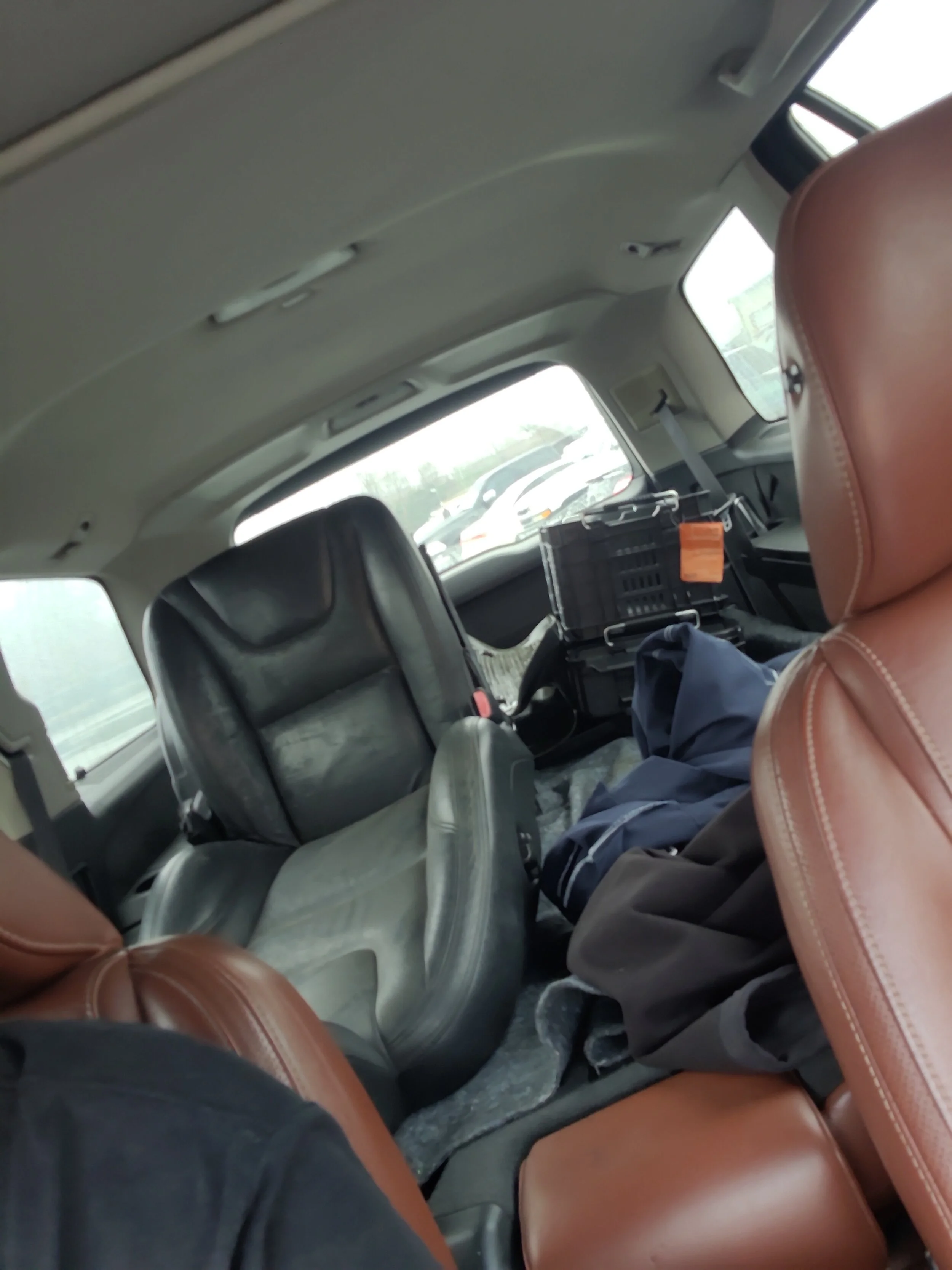
Starting off we need to remove the two regular seats from the cab of the truck, along with the center jump seat. To remove the two main seats you need to first remove the circular covers on the feet.

Photo of one of the rear seat bolt covers. The small trim screws do not need to come off, letting the piece stay attached to the foot. Just remove the center circle with a pick.
There is one on each foot of the seat (4 per seat) and you will now have access to the 21mm bolts that hold everything in place. Undo these 4 21mm bolts.
Now with the seat unbolted, lean it back so you can access the harness. Pull the grey handle down to release the harness from the seat. Repeat this process on the passenger side.
To remove the center jump seat, there are 2 bolts on the back feet which are directly accessible. The two remaining bolts holding the seat in require the bottom hold of the seat to be folded up.

There are trim clips holding the seat bottom down, pop these out and lift to access this area while the seat is in the truck.
With the 4 bolts from the jump seat removed, it can be lifted up and out of the vehicle.
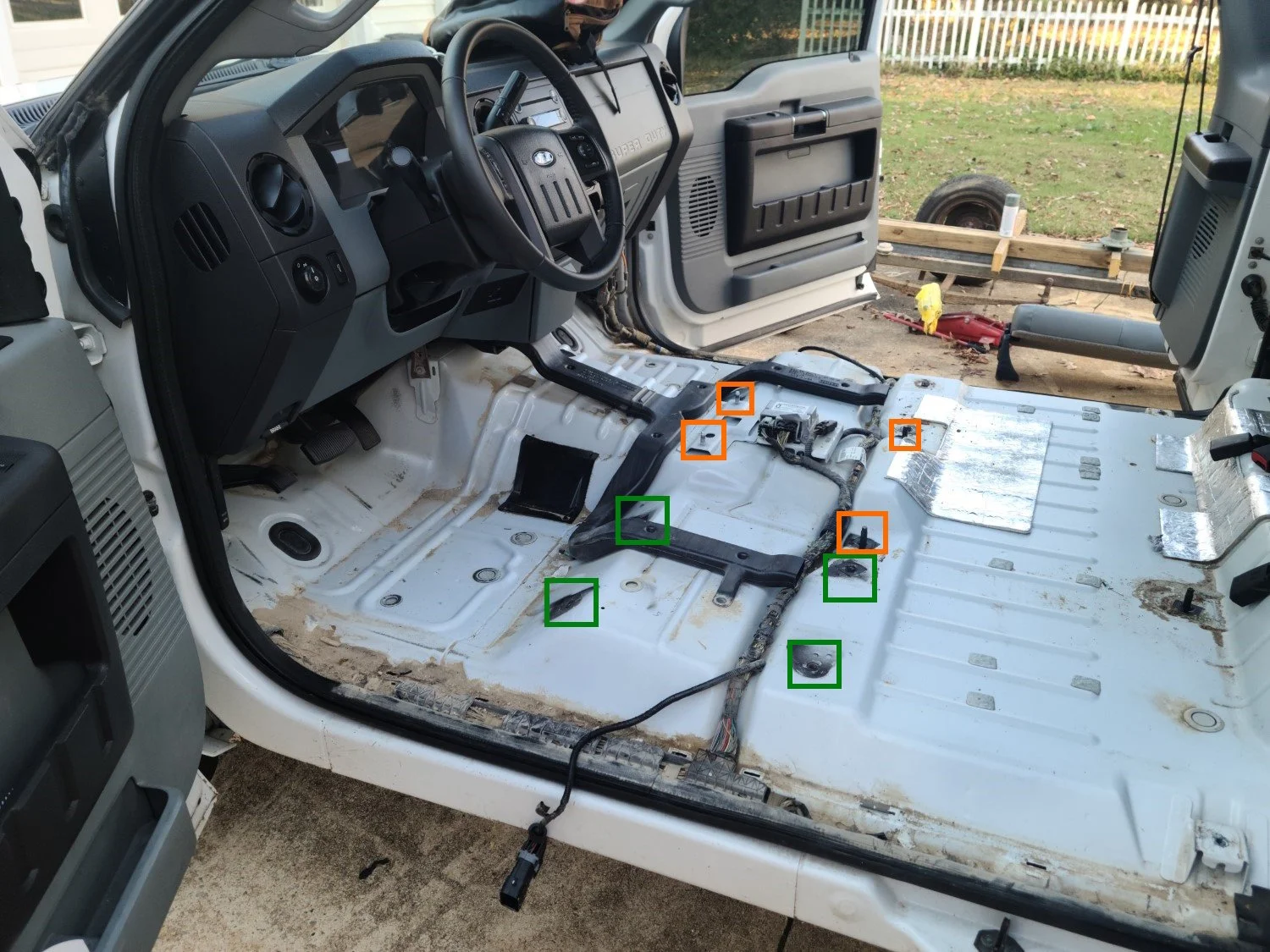
I removed the rubber flooring of my truck to install carpet, but this gives a better view of where the bolting points are in the vehicle.
In the above photo, you can see the green boxes are where the drivers seat bolts through the cab, and the orange shows the 4 standoffs for the middle jump seat / flow through console mounting points.
With the interior space now freed up, I installed my carpet and also ran the 2 lines for the plugs into the center console. These can also be installed over existing carpet since the console would cover them.
The power for the inverter went to upfitter switch 1, which is the solid yellow wire under the dash. As previously mentioned, this is a 25A circuit with its own switch on the dash and fuse, so it should be able to handle the 150W inverter without issues.

Once the wires were in place, I installed the center mounting bracket for the center console. This is held in with 2 of the bolts removed from the jumpseat (the ones under the front of the seat). This is part #4 in the diagram at the top.

The center console mounts to this via 2 7mm bolts on the sides.
With the mounting bracket in place, and the wires run we now need to replace some dashboard trim. From the factory the XL trim trucks have a flip out cup holder below the radio and AC controls, this panel will be replaced with the bezel mentioned in the beginning that needs to be ordered. To replace this, we need to remove the face plate of the dash along with a couple bolts.
This guide does a good shop showing how to access these bolts and get to the panel: https://www.youtube.com/watch?v=AnhCNoWoSBo
While that guide is showing how to install cup holders on an even more basic trim truck, the steps are identical for the new “slot” piece for the flow through console to connect to.
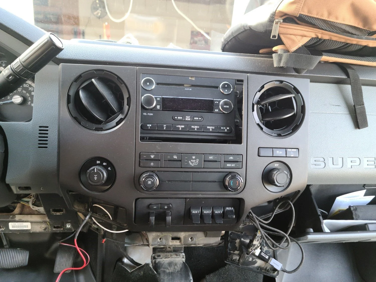
Removing the panel under the steering wheel also makes it very easy to access wiring and everything else youll need to install. The faceplate is held in with 2 7mm bolts and the rest is clips, whereas the bottom cup holder is held in with 3 7mm bolts (one hiding behind the lower part of the panel under the wheel) and two living behind the face plate. Additionally there are the 2 Torx bits in the middle (which you can see the holes for in the above photo) which also need to be removed.

Now it is worth pointing out that my center console came with the front mounting bracket (part #3 in the diagram). This supports the AC vents for the console. Since I was not planning on removing my whole dash to install the piece to have air flow through my console, I removed this bracket and the AC vent piece from the underside of the console.

The removed piece from the flow through console. On trucks where you have AC passing through to the rear vents, this is used to connect to the dash air system. For my setup, it was not needed.
I have not noticed any structural issues with it being removed.

The piece pictured above will need to be replaced. The item to order is mentioned in the beginning, and the lock barrel moves to the small trim piece with 3 5.5mm screws.

Now with the new lower trim piece installed, we can button the dash back up and then slide the center console into place. The two rear feet fit over the existing bolts, and line up the bolt holes on the sides to screw the 7mm bolts into the center support bracket. The console has guide pins which do right into holes in the new dash trim to keep everything aligned.
NOTE: When I re-used the nuts for the rear standoffs the hole in the center console foot was too large and the nut went right through it. I made a small washer for the one side which fixed the issue.

With the center console in place you can put the optional trim pieces over the rear feet. Installing the seats is the same process as removal but in reverse.
Once the seats are back in, the install is done!
Conclusion
There are a few parts of the process I wish I had gotten better photos of. I plan on making a video supplementing this guide which can show some more areas I had any issues with or I want to make even more clear. If you have any suggestions or edits you would like to see made, please leave them in the comments below, thanks!
13-16 F250 Steering Wheel and Audio Control Upgrade / Retrofit Guide for Dummies
Foreward
So since I last did a car related blog post on here, I was adding a trans cooler to my Volvo XC90. Due to it not meeting my needs, and buying a bigger car trailer for the business I decided to upgrade to a 2013 Ford F250, XL trim. This means my truck is about as barebones as it gets. Lots of blank switches, rubber floor vs carpet, etc. Its perfect for my needs around the house and for the business, but in my experience the forums and youtube guides on fixes and upgrades leave a lot to be desired. There is too much fragmentation amongst the different model years, and the truck being made from 1999-2016 means a lot of guides change over time with the chassis. Couple that with the fact that forums exist not only for the different year models, but also by the engine they came with. So with that all being said, here is my definitive guide on how to install an upgraded steering wheel, and add the steering wheel audio controls to a 2011+ Ford F250 / F350.
Prerequisites
Tools you will need:
Windows Laptop
5.5mm Socket
T50 Torx Bit
Basic set of sockets, wrenches, and screwdrivers
Items to Order:
Ford Super Duty Lariat Trim Leather Steering Wheel, PN: DC3Z3600CA
Build Process
To start, we will be replacing the steering wheel. This is a fairly straight forward process so I will not get into the finer details since guides on how to do this are more than plentiful. Removing the steering wheel shroud is required to access the 3 clips holding the airbag on, and this is what we need the 5.5mm socket for. Why Ford used a 5.5mm instead of just a regular Torx bit is beyond me. We can hold off on disconnecting the battery until we have the airbag popped out of its clips since the wheel needs to be turned to access each side.

From here we will remove the center bolt holding the wheel in place. Unlike the Volvos I usually work on, this bolt was in there TIGHT. I used a 1/2in. T50 Torx bit on my impact gun to break it free, even my 3/8 Dewalt couldn’t get it to budge. Keep this in mind for reinstallation.
With everything unclipped and disconnected. we simply reverse the process to add the new steering wheel in. I transfered over my cruise control panel since the new steering wheel came with controls for the Lariat cluster, which has slightly different buttons.

Now with the new wheel and audio controls installed, we need to hop onto our laptop and do some basic programming to get everything to play nicely. There are separate guides on how to get Forscan installed on your PC, but its really as simple as downloading the program, and installing the device driver on your PC. (The unit I linked and used for this comes with very easy to follow install instructions).
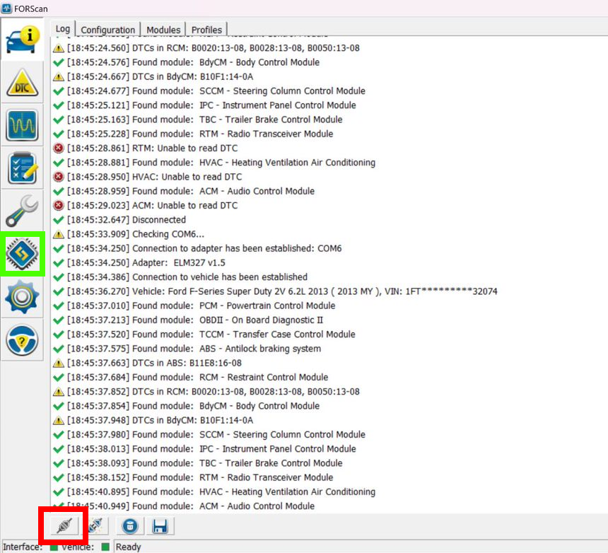
Starting with the red highlighted area, we will connect to the vehicle and read all the modules. Then, clicking on the green icon we will go the the module Configuration and Programming page. We need to change some hex codes for 2 modules. The first one will be the SCCM Module (AS BUILT), select the module and click the play button at the bottom. (Highlighted green) You will be taken to the following screen:

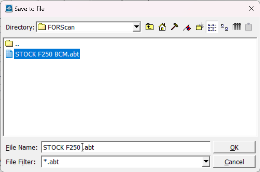
Once in the page we will click the Save All button (highlighted in red). This will open a window where we can save the stock configuration of the module. This is just a precaution incase of a flash failure. Make sure to back these up to a cloud service or onto multiple drives.
Next in the blue highlighted area, we will change the hex data to the follwing:
724-03-01:
0505 0006 3F
Once those 3 fields are changed, click the Write button next to it. Once you have done that, save your configuration again using a different name. Then click the STOP button (next to the green highlighted area), to exit out of the SCCM config page.
Our next step now will be opening the ACM Module (AS BUILT)

Before making the changes, make a backup of the stock ACM config using the save SAVE ALL button as used in the previous module steps.
Now lets change the two lines of data in the blue section:
IMPORTANT Authors NoteS:
(Update 1)
8/7/24 - After doing this configuration, I noticed that my radio lights were not working. This was a fault of the code I used which was pulled from a separate guide. To fix this issue, I found a same year model, higher trim of my truck (in this case my truck being a 2013 XL model, and the “found” vehicle being a 2013 XLT) and replaced the two lines with the as built data from that truck. Here is how I did it:
1. Locate a higher trim model of your truck (XLT+, with Sync is prefered, do not use a truck with the bigger screen option). I used AutoTrader for this.
2. Copy and paste the VIN here: https://www.motorcraftservice.com/AsBuilt
3. Scroll down to the ACM Module As Built
4. Copy the first two lines to your trucks ACM config
(Update 2)
8/14/24 - I had an issue with the codes that I used. While at first everything seemed to be working, after turning my radio off one day, my radio starting displaying NO AUX INPUT FOUND. So clearly there is something wrong with the ACM codes I used. Due to this, I compiled a list of ACM codes I have found from various trucks into this spreadsheet. I will be using a new programming cable and testing these various codes to find which one works best for my system. Once I find one set that works best, I will update the ACM codes below:
727-01-01
0400 90BB A625
727-01-02
0031
With these two lines changed, click the WRITE ALL button (highlighted in green), and then make a backup of your modified ACM.
The two modules should now be successfully changed, so lets try out our steering wheel controls!

Conclusion
This retrofit is a must if you have a base model F250 or F350. Even if you want to keep your stock wheel, you can use this guide to add just the new steering wheel controls as the wheels all have the wiring pre-installed for them, and removal of the blank button is as simple as prying it out. I still need to figure out the phone controls on the wheel and with the radio, but its not a top priority for me at the moment. I hope this guide helps, and please feel free to share it amongst truck groups, or leave a recommendation down in the comments on what could be done better or different.
Misc. Project - Volvo P3 Desk Chair
Foreward
I am in the process of upgrading my desk setup as my current Ikea desk with a piece of plywood over it and a gaming chair isnt the best look in my house. Given the costs of “professional” desk chairs designed for taller people I decided to take it upon myself to build one from a Volvo seat. The project was actually much easier than I thought, and If I had to build another there are a few changes I would make.
Prerequisites
Tools you will need:
Angle grinder
Bench grinder (to remove burrs) or grind stone for angle grinder
Wire strippers
Misc. Torx and metric sockets
Flat blade screwdriver
Straight blade pick (I use the $1 ones from Harbor Freight)
Drill and 1/4inch drill bits (you can use whatever size you like, 1/4 was easy and fit through the stock frame holes)
Paint (I used STEELIT)
Items to purchase:
Volvo P3 seat. This can come from any model, the bases are all the same. Heated seats can be found in most models, heated and cooled seats can often be found in S80s.
Desk chair with basic base. Some desk chairs have multiple adjustments and plastic bases. I went with the most basic, free desk chair I could find on Marketplace. You want to also find one with the lowest rise you can, as the base of the car seat adds significant height which shorter people may find uncomfortable.
1/4in. thick steel bar stock / rectangular steel tube. I will touch more on this in the build details, however Stock Car Steel and Aluminum can cut and ship any size of steel you need for your projects without needing to visit a mill or buy huge pieces of steel!
Build Process
I started this build with the seat! These are relatively easy to find depending on where you are in the country. I went to a local DIY pull-a-part junkyard and paid $40 for my seat. The seats are held into the car with 4 bolts under plastic covers. I then used snips to cut the wires going to the harness of the seat, so I had wires to work with. The seatbelt an be unbolted from the seat frame, or in my case I just cut the seatbelt with my snips since I wasnt going to need it. This seat was not heated or cooled, so I will not be going into adding controls for those functions.
With the seat loaded up in my XC90 I headed back home to start prepping the chair for minor modifications.

I will be reusing this image, but the harness bolts into the chairs female harness, the wires usually come wrapped in tesa tape which I removed. I kept about 8 inches of pigtail harness.
With the seat now removed from the car, the first modification is making the rails completely flat. Each end has a bracket that is welded onto the slider so it can bolt into the car. With my design I needed these out of the way, leaving a perfectly flat rail on each side of the seat.

FOR VISUAL REPRESENTATION, THE SEAT DOES NOT NEED TO BE REMOVED FROM THE RAILS
I didnt take any of my own photos for this project (so I am using this photo of P2 rails which are close). There are brackets on each corner that I used my angle grinder to cut off from the rails. These only take a few minutes to cut through and make the bottom of the seat perfectly flat.
Once I had this done, I moved onto testing and fabricating the electronics to make the power functions work. On the P3, this is very easy and consists of a 12v power, a 12v signal wire, and a ground. I would consult the Volvo wiring diagram for your own seat to confirm which wires are needed, so for this case this applies to all 2011+ S60s (and probably V60s).
Here is the diagram I followed with my notes on what you need:

74/31 is the 20 pin connector that runs from the car to the seat. The only 3 pins you need to worry about on the car side of the harness are pins 14, 15, and 16.
Pin 14: Blue / White is a signal wire from the CEM, this is a signal to the Stop Logic to allow the seat to move. Connect 12V to this wire.
Pin 15: Brown / Red is 12V power to the seat control module (3/27). Connect 12V to this wire.
Pin 16: Black / Green: This is ground for the module.
A side note regarding the other pins, SRS module, and air bags:
There is some concern by some that there is a danger in not removing the air bag from the side of the seat. The route I went to avoid incidents was to remove any and all wiring in the pigtail going to these modules. All of the pins outside of the 3 listed above can be removed, and is why the small straight pick is listed in the parts list. You can remove the small red caps from each pin and use the pick to lift the clip and slide the pin end out. Additionally, the airbag firing system needs a signal from the OWS or Occupant Weight Sensor. Going off the wiring diagram, if the OWS does not have power, even if power was sent to the airbag firing system it would not deploy since it needs the circuit completed by the OWS signal.
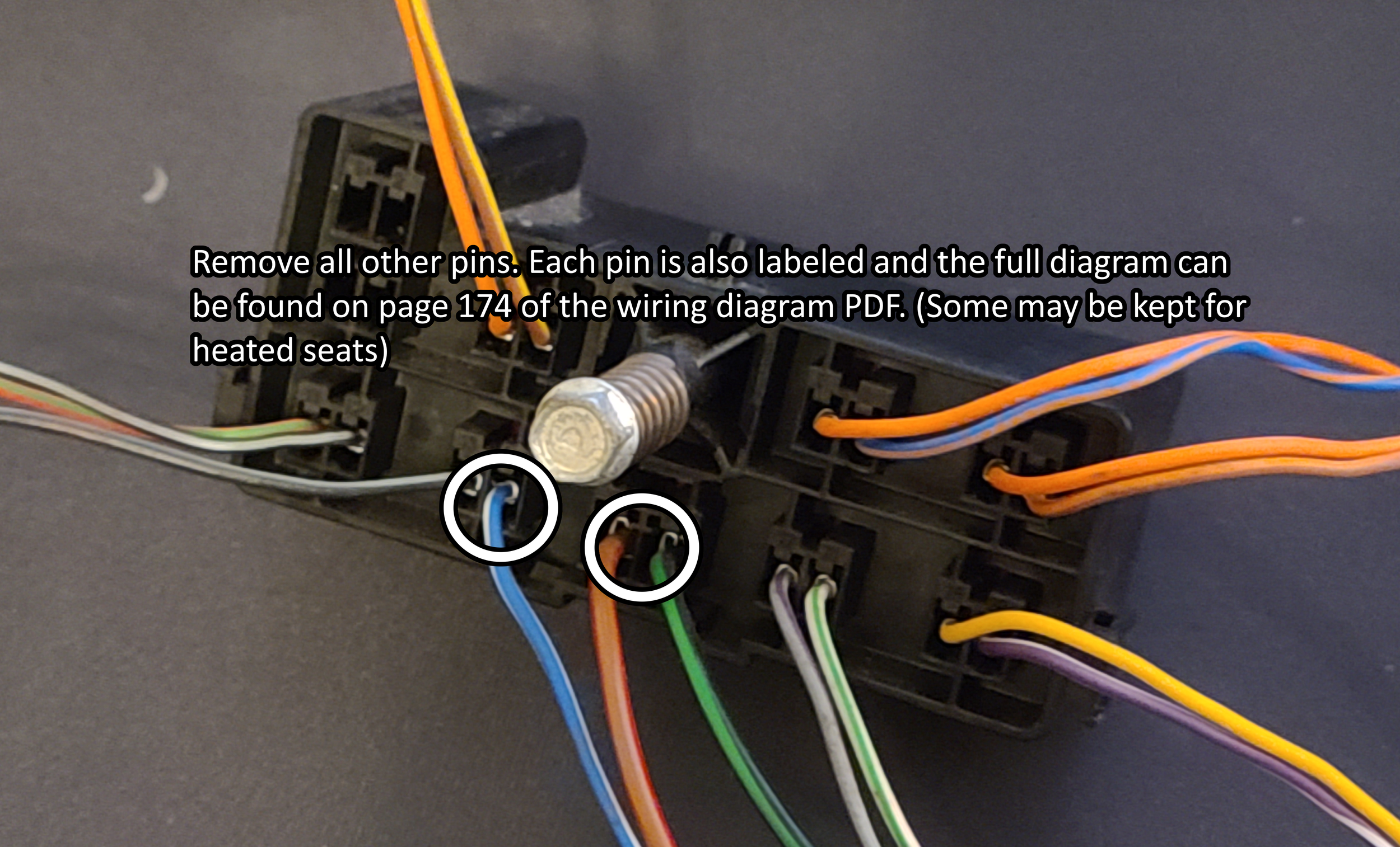
Be sure to remove the black/grey cable next to the white/blue cable as it is part of the airbag firing system!
Now you may be asking yourself well how do I apply 12V to these wires when the walls in my house put out 120V AC? Well for that we need the cheap adapter brick I linked at the top of the page. The unit I bought came with a barrel jack to screw terminal adapter which we will connect the 3 wires from out pigtail into.

I trimmed about 1/2in. from the end of each wire with my wire strippers, and twisted the 2 positive wires together at their end before inserting them into the connector. I put some electrical tape over everything before tucking it up into the seat just for extra protection. The power brick I then attached under the seat with some zip ties and tucked all the wires away.
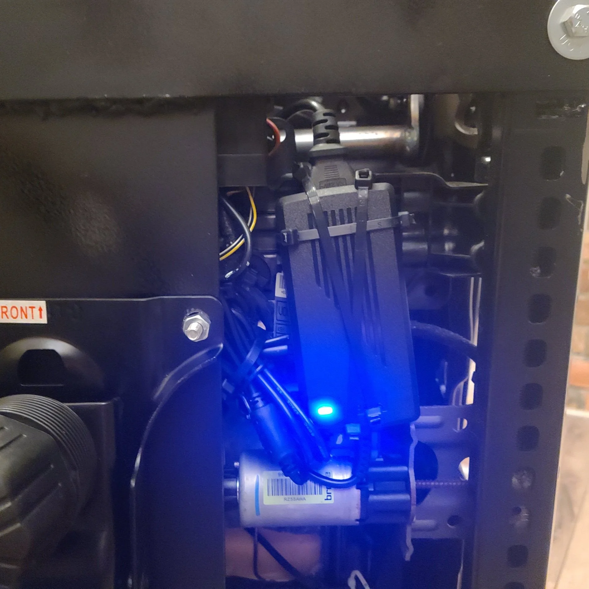
The power brick, zip tied under the chair inside the original seats rails with the other components.

The de-pinned connector to the seat.
With the electrical fully sorted, I then turned my attention to mounting the seat to the rolling chair base. I made sure to pick a donor office chair that had minimal adjustment points, and a standard 4 bolt base. Some higher end chairs have multiple pivot points and more complicated bases. I used a piece of ~8inch wide by 1/4inch thick steel flat bar. (Measure your base width before buying material) I went with what I had on hand at work in our scrap bins, otherwise I think I would have gone wider for stability. I then measured the distance between the rails both front and back and cut two more pieces of 2inch by 1/4inch steel flat bar to make my cross members. I mocked everything up with the seat sitting on the metal and the metal on the chair base so I could line everything up properly and make marks on where I needed to drill mounting holes and where the cross bars would need to sit. I did not do any crazy measurements here, just got everything looking “right” and marked parts with a paint pen so I could disassemble and bolt / weld everything together.

I (poorly) welded my brackets, however bolts could also be used to hold the cross members in place.
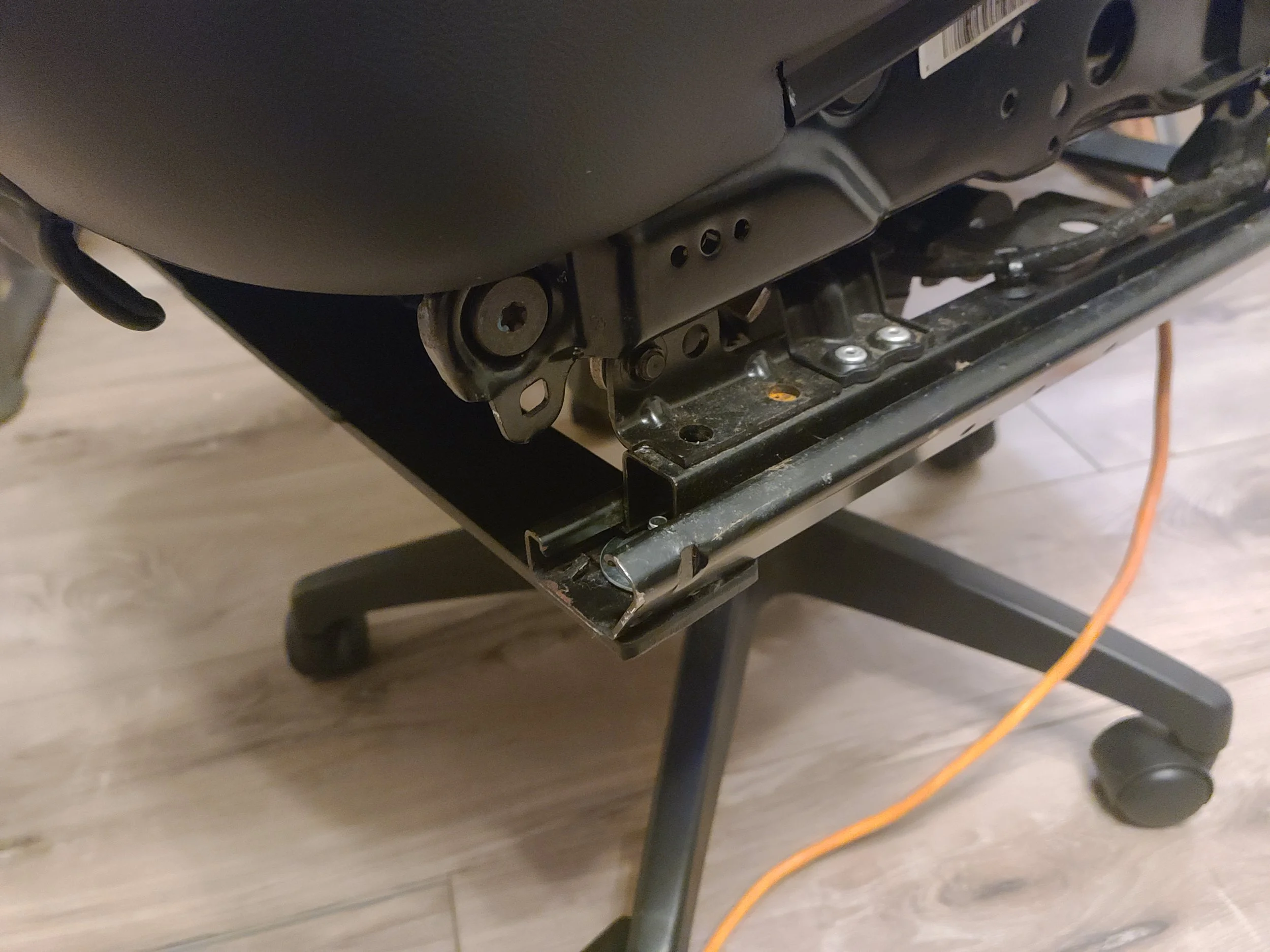
Here is the bracket mid construction. I still needed to drill the holes for the rails to bolt to, and I gave it a coat of flat black STEELIT paint. I also ended up flipping the bracket over in installation to lower the seat rails a bit to buy myself some lower seating position. Like I have previously mentioned these chairs sit very high compared to a standard chair due to all the motors underneath them, so choose your base chair wisely.

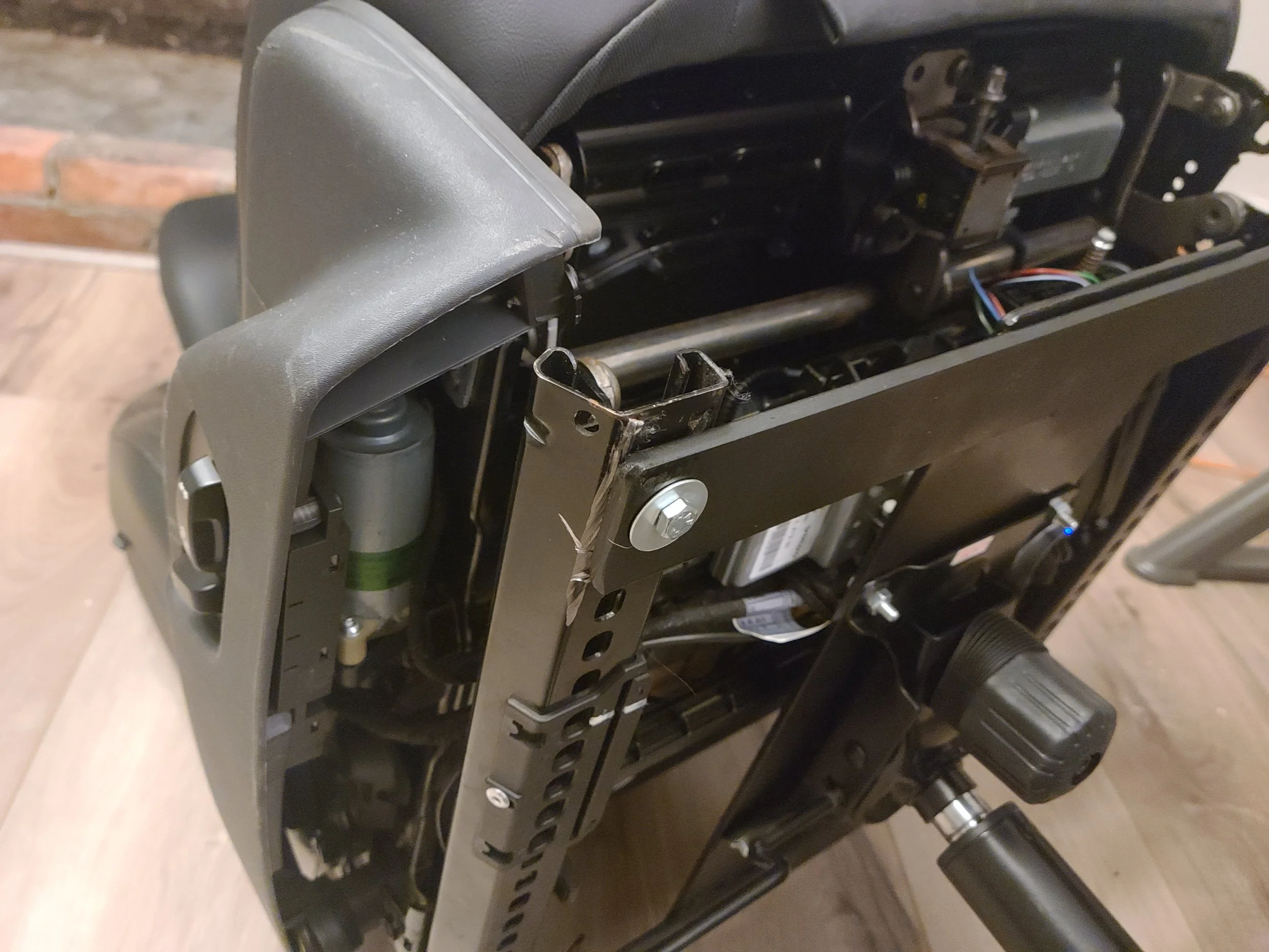

All of the hardware used was 1/4 inch bolts from Lowes. I also used some stacked washers on the front bolts for the frame rail since the hole for the original bolts in the car are quite large.
The last thing I did was run an 8ft "designer” extension cord out of the back of the seat from the power adapter and left all the slack in the seat back pocket. This will allow me to plug it into my desk without having to run the long extension cord from my wall to the chair, and it can be neatly tucked away inside the seat back pocket when not in use.

Conclusion:
There are a few things I would change about this build. The first thing is that I would have used a mild rectangle steel square tube instead of flat bar for the cross members. With the way I flipped the bracket upside down this would NOT have added any extra height but would have added some extra stability side to side. Additionally a higher quality base would have been nice to use as there is some play with the sheer amount of weight its now carrying. Lastly, I still plan on adding arm rests using some generic bolt on arm rests from Amazon, I just need to get around to ordering them and possibly adding some more brackets to allow them to attach where I need to.
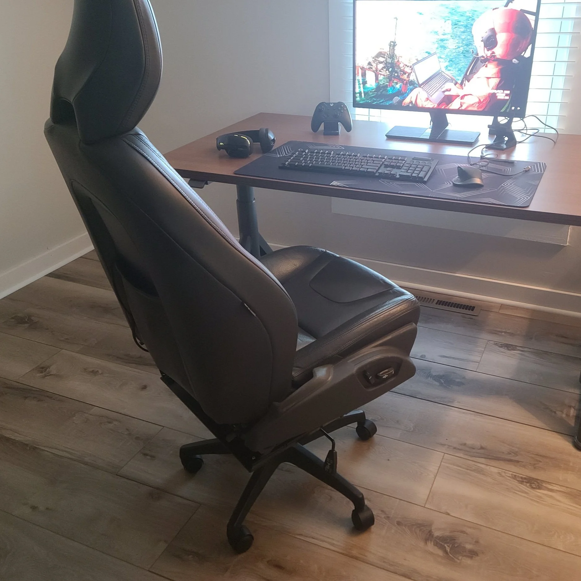
I hope you all enjoyed this little project, it completely blew up on Reddit which I did not expect! For a 2 day project that I sort of made up as I went I am very pleased so far with the outcome. If you have any suggestions please feel free to leave them down in the comments.
Archive
-
2025
- Dec 15, 2025 11-16 Ford Super Duty Remote Start Ultimate DIY Guide Dec 15, 2025
- May 5, 2025 Volvo 700 Series In-Tank Fuel Sender Assemblies - Whats the deal? May 5, 2025
- Apr 28, 2025 Store Update: Shipping Rates and Carriers Apr 28, 2025
- Jan 1, 2025 Cash for Clunkers and Todays Car Marketplace - A Mathematical Analysis on Why Cash For Clunkers Doesn't Matter Anymore. Jan 1, 2025
-
2024
- Nov 25, 2024 11-16 Ford F250 / F350 Super Duty - Definitive Flow-Through Center Console Install Guide Nov 25, 2024
- Jul 30, 2024 13-16 F250 Steering Wheel and Audio Control Upgrade / Retrofit Guide for Dummies Jul 30, 2024
- Mar 13, 2024 Misc. Project - Volvo P3 Desk Chair Mar 13, 2024
- Jan 16, 2024 The Definitive P2 XC90 External Transmission Cooler Writeup Jan 16, 2024
-
2023
- Aug 8, 2023 TFT Display with P3Tool Guide Aug 8, 2023
- Aug 4, 2023 Facility Upgrades and Updates Pt. 2 - Tow Dolly Aug 4, 2023
- Mar 27, 2023 Facility Upgrades and Updates Pt. 1 - John Deere 165 Hydro Restoration Mar 27, 2023
-
2022
- Sep 27, 2022 P3Tool - Volvo Hacking Takes Its Next Big Step Sep 27, 2022
- Aug 25, 2022 Project Nashville Pt. 3 - MOST Excelent! Aug 25, 2022
- Jun 28, 2022 NordCarolina Shop Update! Jun 28, 2022
- Jun 20, 2022 Project Nashville Pt. 2 - Tech Talk Jun 20, 2022
- May 12, 2022 And I Would Drive 500 Miles - Project Nashville Pt. 1 May 12, 2022
- Mar 14, 2022 On life, cars, and business. Mar 14, 2022
-
2021
- Jul 19, 2021 Volvo 960 Project Pt. 6 - Still Alive Jul 19, 2021
- Mar 12, 2021 Volvo 780 Bertone Project Pt. 2 - Why buying another persons project is the WORST. Mar 12, 2021
-
2020
- Dec 7, 2020 Volvo 780 Bertone Project Pt. 1 - In Over My Head Dec 7, 2020
- Dec 7, 2020 Volvo 960 Project Pt. 5 - Taking my time. Dec 7, 2020
- Sep 11, 2020 A Very Volvo September Sep 11, 2020
- May 15, 2020 960 Project Pt. 4 - End of Spring Almost Summer Updates May 15, 2020
- Feb 3, 2020 960 Project Pt. 3 - Always Remember Your Oil Feb 3, 2020
-
2019
- Dec 17, 2019 Nord Carolina - Starting my own E-Commerce Platform for Volvo Enthusiasts Dec 17, 2019
- Nov 20, 2019 960 Project Pt. 2 - I built it one piece at a time... Nov 20, 2019
- Oct 2, 2019 960 Project Pt. 1 - Diving In Oct 2, 2019
- Sep 20, 2019 1997 Volvo 960 Project Pt. 0 - $800 Worth of Headaches Sep 20, 2019
- Aug 3, 2019 VDASH Pt. 2 - Cloud Based Car Tuning Aug 3, 2019
- Jul 2, 2019 VDASH Pt 2. is coming.... Jul 2, 2019
- Apr 1, 2019 VDASH Pt. 1 - A new tool for a modern Volvo hacker Apr 1, 2019
- Mar 18, 2019 2013+ Shifter Retrofit Project Pt. 2 - Reconstruction and Installation Mar 18, 2019
- Feb 17, 2019 2013+ Shifter Retrofit Project Pt. 1 - Preparation and Disassembly Feb 17, 2019
- Feb 2, 2019 The P3 Common & Uncommon Repairs Documentation Project Feb 2, 2019
-
2018
- Dec 28, 2018 Mini-Post: New side skirt. Dec 28, 2018
- Dec 8, 2018 Driveability and Performance Report: December 2018 Dec 8, 2018
- Oct 8, 2018 Audio Modules & The Return to Boostmoose Oct 8, 2018
- Jul 28, 2018 The Final Report: 850R Beauty Shots Jul 28, 2018
- Jul 17, 2018 Mid-July Summer Update Jul 17, 2018
- May 15, 2018 Summer Progress Update May 15, 2018
- Apr 1, 2018 850R - Stage 0 Dreams Pt. 2 Apr 1, 2018
- Mar 18, 2018 850R - 960 Throttle Body Upgrade pt. 1 Mar 18, 2018
- Mar 14, 2018 850R - Seat Restoration Mar 14, 2018
- Jan 18, 2018 S60R - Wrap Repair + Driving the Eastern Shore Jan 18, 2018
- Jan 1, 2018 S60R - Vinyl Wrap Jan 1, 2018
-
2017
- Dec 4, 2017 850R - Better and Brighter Tail Light Installation Dec 4, 2017
- Dec 4, 2017 S60R - Holiday Charity Laps at Virginia International Raceway Dec 4, 2017
- Nov 16, 2017 850R - Junkyard Pulls for Performance & New Rear Lights Nov 16, 2017
- Nov 15, 2017 S60R - Scheduled maintenance.....yawn. Nov 15, 2017
- Nov 3, 2017 850R - Stage 0 Dreams Pt. 1 Nov 3, 2017
- Nov 1, 2017 850R - Firestone Fixes CV Axle while Suspension Nears Completion Nov 1, 2017
- Oct 28, 2017 850R - Axle Removal and CV Boots Halt Progress Oct 28, 2017
- Oct 27, 2017 850R - Air Tool Woes and Broken Brakes Oct 27, 2017